Bending Moment Diagram for Cantilever Beam
Shear Force and Bending Moment Diagram for Cantilever Beam with Udl. DM x a V x P 58 dx L These expressions for the bending moment and shear force can now be plotted against x to produce the Shear Force and.

Pin On Xx
Shear Force wL.

. Once the forces and moments are calculated the design of the element needs to be done. In this video i explain step by step procedure for drawing shear force and bending moment diagram. Therefore bending moment diagram of a beam carrying an UDL between two points will be a parabolic.
Over the Whole Span. Cantilever is the type of beam having fixed support at one end and free at. A cantilever beam is a type of beam that has simply support on one side and.
In this case the shear force is constant throughout the length of. Cantilever beam External moment formulas Now before we get started. A bug concerning failure of the code to return the equations of bending moment and shear force from the beginning of the beam was fixed.
It is equal to the algebraic sum of moments of all forces including that of reaction either to the left or to the right of the cross-section about the section. Cantilever beam Triangular load formulas 8. Generally in the case of cantilevers the shear force and the bending moment will be maximum at the supports.
This video explains how to draw shear force bending moment diagram in case of propped cantilever beamPropped cantilever beam is a beam which is supported. This video shows the shear force and bending moment diagram for a cantilever beam. As the SFD shear force diagram is a triangle therefore the beam will be loaded with uniformly distributed load UDL Also there is a sudden increase in shear force from -6 kN to 14 kN.
The cantilever beams serve to produce a bending effect within specific limits. So bending moment at any point will be equal to the. 54 the shear force equation is.
Bending moment diagram. Without understanding the shear forces and bending moments developed in a. In the other words.
These types of beams transfer the load to the support where they can manage shear force and bending. When a moment is applied at the free end of a cantilever it will be transferred by constant magnitude to the fixed end. This video explains how to draw shear force diagram and bending moment diagram with easy steps for a cantilever beam loaded with a concentrated load.
Drawing of beam diagrams for a cantilever beam with point load. Cantilever beam 3 Point loads formulas 7. Design of Cantilever Beam.
Bending Moment wxL x L 2 wL 2 2. This is a problem. After evaluating the loads applied to the beam bending and shear forces can be calculated from the.
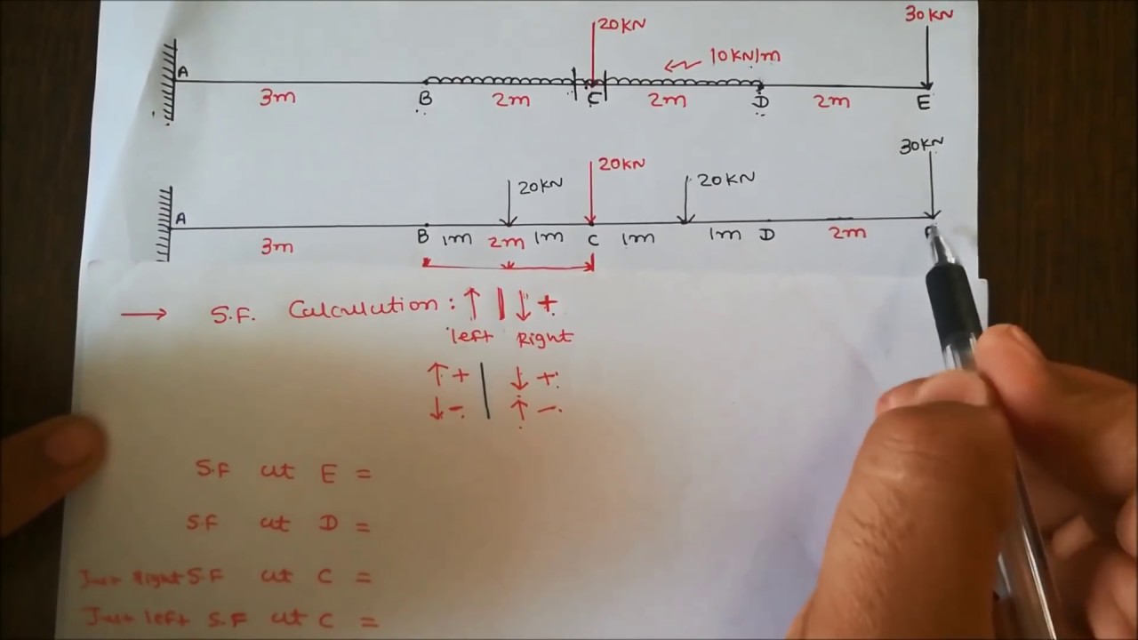
Jul 23 2021 Download the DegreeTutors Guide to Shear and Moment Diagrams eBook. In this video we are Going to Learn about How to solve problems on Shear Force diagram SFD and Bending Moment Diagram BMD for cantilever beam with two Point Loads.
338 Shear Force And Bending Moment Diagram For Cantilever Beam Youtube Shear Force Bending Moment In This Moment

Way To Draw Shear Force And Bending Moment Diagram In Case Of Cantilever Beam Bending Moment Shear Force Civil Engineering Design

Cantilever Beams Moments And Deflections
Cantilever Beam Calculator Calc Resource Civil Engineering Design Structural Design Engineer Structural Engineering
0 Response to "Bending Moment Diagram for Cantilever Beam"
Post a Comment